B2G/Wifi Display
Current Status
There are gecko/gaia development branches to support Wifi Display (for some degree) on B2G:
- Gecko: https://bitbucket.org/changhenry/mozilla-central/branch/dev%2Fwfd2
- Gaia: https://github.com/elefant/gaia/tree/dev/wfd2-amd
Flash the above branches and go to "Settings" --> "Wifi Direct", click the sink you want to use then you will be Wifi Display-ing!
Web IDL
Introduction
Wifi Display (a.k.a. Miracast), is a screen cast standard defined by WiFi Alliance. With Miracast-enabled device such as smart TV or Miracast dongle, one can project his/her screen (usually on a phone) to the TV or a bigger display. We call the device to cast the content the "source" device; the one to display the content is called the "sink" device.
The remote displaying content is not necessary to be identical to the local one. When two screens show the same content, it's known as "mirror mode". Mirror mode is the most common use case when it comes to Wifi Display. In fact, Wifi Display doesn't define "what to display" but "how to display". People would usually like to use Wifi Display to display:
- The "exact" mirrored screen, which means the same content, the same dimension and the same resolution.
- The "modified" mirrored screen, which is basically the same content but with overlay or without some secret information. (Content may be also re-rendered by the different dimension.)
- The extension of the screen. (Imagine the extended desktop on Windows.)
- The application specific content. (For example, for a racing game, main screen on the big remote display and the mini map on the local, small screen)
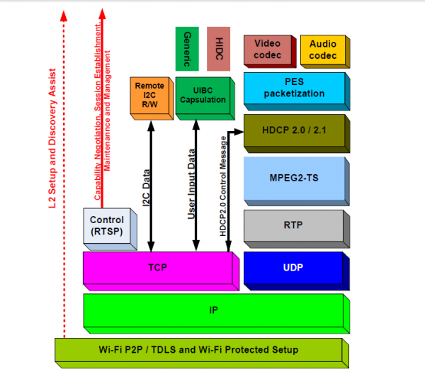
Wifi Display consists of a couple of existing technologies, including Wifi Direct (or TDLS) as the communication channel, H.264/AAC as the codec requirement, RTSP as the streaming protocol, etc. The following figure shows the full stack:
Here we are briefing each layer from top down:
- The topmost layer is definitely the audio/video presentation, which is required to encode as LPCM/AAC and H.264 respectively.
- MPEG2-TS is the container format used to frame the encoded audio/video.
- The MPEG2-TS data will be carried by RTP packet and sent to the client in corporation with RTCP. RTP in conjunction with RTCP is typically called RTSP.
- TCP/UDP/IP is the layer underneath RTSP to transport data.
- Wifi Direct/TDLS is required to establish the link between sink device and source device. (Even though the entire stack atop could be over the network link built from whatever method.)
Architecture
Overview
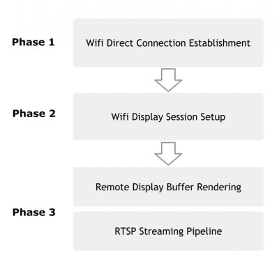
The scenario of Wifi Display is not a single step but a series of actions, such as enabling Wifi Direct, picking up a sink device then establishing connection, and rendering whatever content for remote displaying (usually the mirror of your screen). We divide the function of Wifi Display into 3 major phases:
Phase 1: Wifi Direct Connection Establishment
In this phase, the user will be asked to choose a remote device to perform Wifi Display since there might be a couple of available devices surrounding you. It can be considered as a ordinary Wifi Direct connection establishment from the user's perspective of view. That means, user may be required to enter pin code or push button to get the target peer device paired. In the Wifi Direct internal, only the peer devices which support Wifi Display sink should appear in the list. Once the connection is established, everything magic happens behind the scene without user's intervention.
Phase 2: Wifi Display Session Setup
After establishing the Wifi Direct connection, the source device will open a RTSP server and listen for the only one permitted sink device to connect. The sink and source device then exchange information and capability via RTSP protocol. Upon completing the handshaking, a Wifi Display session is setup.
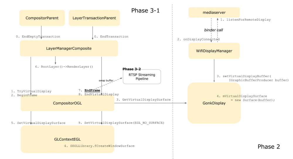
In the current implementation, we directly use a binder call to mediaserver to be listening for the sink device. Once the sink device is connected and the session is setup, mediaserver will call back with a IGraphicBufferProducer. This IGraphicBufferProducer will be used to create a Surface object and stored in GonkDisplay for later use (See mVirtualDisplaySurface in the rectangle "GonkDisplay").
Phase 3: Virtual Display Rendering and RTSP Streaming Pipeline
In phase 2, we target at initiating a Wifi Display RTSP session and obtaining IGraphicBufferProducer. The main purpose in this phase is to "play" around the IGraphicBufferProducer we got earlier on. What we paint on the IGraphicBufferProducer will be sent to the RTSP streaming pipeline and displayed remotely. There are different strategies for different use cases to render the buffer producer. For example, in the "mirror mode" case, we can choose to render the compositor outcome to the buffer producer at once or on a layer-ly basis. Different approaches will be discussed in the following sections.
Wifi Direct
Please refer to https://wiki.mozilla.org/B2G/Wifi_Direct for Wifi Direct basic.
RTSP Streaming
Media Codec
Graphics
Graphics might play the most important role in Wifi Display. We need to double the loading of either CPU, GPU or hardware composer no matter what since there is virtually an additional screen to deal with! Different display mode would lead to different approach. Take the "exact mirror mode" for example. For exact mirror mode, there are typically two approaches: the most intuitive one is to copy directly each composition result to the display buffer. This approach effectively reduces the effort of traversing the entire layer tree (CPU) and avoids GPU doing complicated rendering twice. The second possible approach is to traverse the layer tree twice and send GL commands with different GLSurface. The downside of this way is obviously doing the same thing repeatedly. However, since most of the GL command is asynchronous, we don't need to wait until the current composition result has come out before being able to process the remote display buffer. We currently implement the layer-based solution which will be illustrated later.
Other than mirror mode, the remote display can be also used to show the completely different content from the sink's screen. In this case, we most likely have to maintain two layer trees. The approaches we mentioned before consider only single layer tree. It's a big topic when the number of layer tree grows.
Approach 1 (Composition-based)
The concept of this approach is quite simple: instead of re-rendering the same (almost) things, we just render once and copy the composition result to the virtual display buffer. This can be naively done by waiting for GPU composition result and memory copy to the destination. From the early experiment result, the naive implementation of this approach is definitely not working. The early experiment issues a glReadPixel command for each frame and the fps becomes around 15 even without running Wifi Display. To polish the naive implementation, we need to 1) copy buffer as close as the time when source is ready and 2) use GPU to do the copy. This is still under investigation.
Approach 2 (Layer-based)
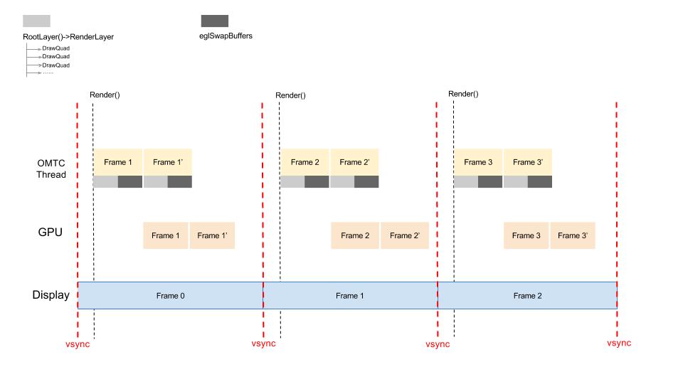
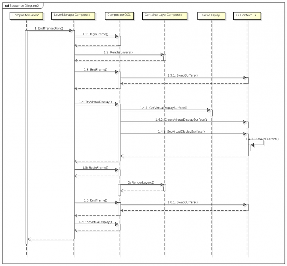
The layer-based approach would traverse the layer tree twice with difference transform matrix and request the GPU to draw on different EGLSurface respectively. We implement this approach like the following figure suggests: in each CPU/GPU frame processing cycle, there is a run for the "primary display" followed by the "virtual display" run. The consumer of GPU in the "virtual display" run is the encoder instead of HWComposer/FrameBuffer. Other than that, most of the operations are identical in the two runs.
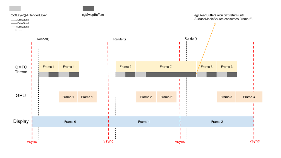
We tested on flame v188 and nexus 4 KK. Statistics showed the fps can still reach 60 on nexus 4 but less than 20 on flame. After profiling each stage of the frame processing, we found that eglSwapBuffer took too much time in the virtual display run. This might be due to the poor codec power on flame. Take Frame 2' as the example. Even if Frame 2' is complete before the next scheduled Render() task, we might still need to wait for the encoder to consume the frame and cause the compositor thread blocked.
To mitigate the blocking issue, parallizing the sequential two runs of rendering/swapping might help. However, it will introduce the synchronization and threading issues and we still have no time to investigate it yet.
